How To Remote Control a RV Camper Trailer Using Motorized Wheel Chocks
- May 25
- 11 min read
Updated: Jun 11
I pull a 19ft hybrid camper with dual axles using a Mercedes Sprinter Van. Due to the overall length of the Sprinter van, backing up the trailer into tight campsites and our driveway can be challenging. I've been dreaming of being able to unhitch the camper and drive it into its parking spot by remote control. That would significantly reduce the amount of time and frustration it can take to get the camper perfectly situated.
The camper usually needs to be leveled by putting leveling blocks behind the tires and driving over them. This further increases the complexity of parking the camper.
The chocks need to be added to the wheels to prevent the camper for rolling away and further stabilize the camper.
EXISTING DESIGNS
While researching parts for our design, we came across this existing trailer mover design that used the same type of friction wheel drive that we were planning to use. Their system is permanently frame-mounted and is engaged or disengaged with the tires either by hand or automatically through the remote control.
The price is for one set of axles. A tandem trailer requires 2 sets, doubling the price to between $3000 to $5000 depending on the model.

A motor with a worm-drive gearbox is visible in some of their models that lack a cosmetic cover. The worm drive gearbox provides very low RPM and self locking (non-backdrivable).
WHEEL CHOCK DESIGN INSPIRATION
Since wheel chocks of some type need to be added anyway, I was thinking that X-style chocks could be motorized by replacing the pads that touch the wheels with rollers. Install the motorized chocks, drive the camper trailer into it's parking spot using the motorized chocks, leave them on to lock and stabilize the camper. They are left on for the duration of the stay. When it's time to leave, use them to drive the camper out to a more convenient hitch-up spot. Drive the camper tongue directly over the tow vehicle's hitch, hitch up, remove the chocks and stow them away. Installing and removing the motorized chocks is no more work than regular wheel chocks.
This is an example of X-style wheel chocks used on dual-axle camper trailers.

These chocks are compact as seen here. The motorized ones would need to be much larger to accommodate the drive rollers, motor, additional strength, and better overall grip on the wheel since they will be rotating.

NOTE ON TURNING
Keep in mind that this is a tandem axle trailer; it is not a good idea to "skid steer" the trailer. That applies a lot of stress to the axles and will grind the tread off the tire if it is done on pavement. It's important to always be moving the trailer forward or backward while turning. Don't turn it in place. Turn it as if you were driving it with a truck.
INITIAL DESIGN
This is a preliminary layout for the motorized chocks.
The specs for the tire are:
An ST205/75R14 trailer tire measures roughly 26.1 inches in overall diameter and 8.0 inches in section width. This radial tire is designed for 14-inch rims and typically features an 8-ply (Load Range D) rating, supporting a maximum load capacity of approximately 2040 lbs at 65 PSI.


There are 2 drive rollers linked with a chain. The drive rollers drive both wheels, making the camper 4 wheel drive! In the following image, one of the side panels is hidden to show the sprockets attached to the wheels. A chain would go between the sprockets.

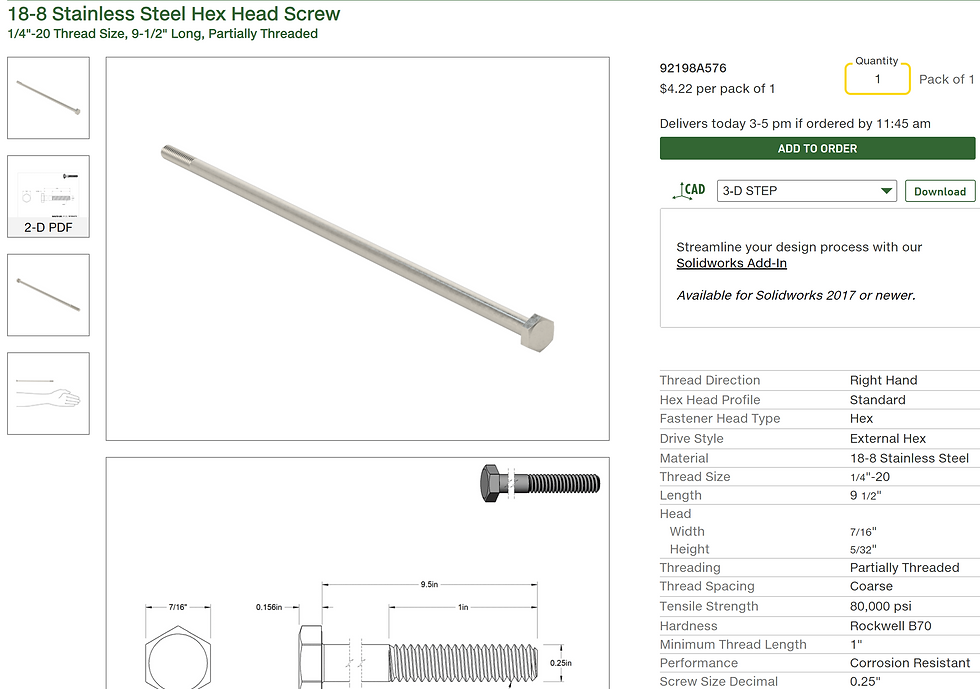
This is the sprocket used in this design:

This is the bolt that passes throught he sprocket and roller:
CHAIN
#35 chain should be suitable for this application.
A standard ANSI #35 roller chain (featuring a 3/8 inch pitch) has an average tensile strength of approximately 2,315 to 2,430 lbs and a maximum recommended working load of about 485 to 560 lbs. It is commonly used for light machinery, go-karts, and mini-bikes up to roughly 15 – 20 hp.
Chain Strength Specifications
The exact strength metrics depend on the manufacturer and chain grade:
Average Tensile Strength: 2,300 - 2,430 lbs
Maximum Working Load: 485 - 560 lbs
Pitch (Pin to Pin): 0.375 in (or 3/8 in)
Roller Width: 0.1875 in (or 3/16 in)
TIGHTENING MECHANISM
Tightening the chocks would be done the same way as the standard wheel chocks. Some extra linkages and a lead screw running down the center.
IS IT POSSIBLE? WHAT ARE LIMITATIONS OF PHYSICS? HOW STRONG DOES THE MOTOR NEED TO BE?
Before we move any further, I wanted to do a quick reality check to make sure the motor size, gear ratio, RPM, and friction roller design were actually practical. In the past I would have had to do all these calculations by hand, which would have taken forever. Now I can use AI chat to get rough estimates very quickly.
A 2in diameter roller turning at 75 RPM against the tire, the max speed witll be 0.45 mph. That seems like a good max speed.
How many watts to move 4000 lb tandem axle trailer on flat smooth ground at 0.45mph?
To calculate the power required to move your trailer, we have to look at the force needed to overcome rolling resistance. Since you're moving at a very slow crawl (0.45 mph) on flat ground, we can ignore air resistance (drag) and focus entirely on the friction between the tires and the pavement.
1. The Variables
First, let's convert your measurements into standard units for the physics formulas:
Mass (m): 4000 lbs≈1814 kg
Velocity (v): 0.45 mph≈0.201 m/s
Gravity (g): 9.81 m/s2
Rolling Resistance Coefficient (Crr): For a typical trailer tire on smooth concrete/asphalt, this is roughly 0.015.
2. The Calculation
The formula for Power (P) in Watts is:
P=Frr×v
Where Frr (Rolling Resistance Force) is:
Frr=Crr×m×g
Step A: Find the Force
Frr=0.015×1814 kg×9.81 m/s2≈267 Newtons
Step B: Find the Power
P=267 N×0.201 m/s≈53.7 Watts
3. The Reality Check
While the math says you only need about 54 Watts (roughly the power of a dim incandescent light bulb), there are three big "real world" factors that will significantly increase your power requirements:
Inertia (The Start): It takes much more energy to get the 4,000 lbs moving from a standstill than it does to keep it moving.
Drivetrain Efficiency: If you are using an electric motor or a "trailer valet," you lose energy through the gears and motor heat. Most small electric tugs operate at about 50–70% efficiency.
Surface Imperfections: Even a small pebble or a 1-degree incline will cause the power requirement to spike instantly.
Bottom Line: While it technically takes ~54 Watts to maintain that speed, you would want a motor rated for at least 250–500 Watts to handle the initial "breakaway" force and minor surface bumps.
How many watts if the tire is driven by a 2in diameter friction roller pressed into the surface of the tire?
When you switch to a friction roller drive (a small roller pressing against the tire), the theoretical power required to move the trailer stays the same, but the actual power required from the motor increases due to mechanical losses inherent in that design.
To maintain that same 0.45 mph speed, you would need approximately 75 to 90 Watts at the motor shaft.
1. Why does the wattage go up?
The "useful work" being done is still just overcoming the trailer's rolling resistance (~54 Watts). However, the friction roller introduces two new sources of energy loss:
Hysteresis (Deformation Loss): To get enough grip to move 4,000 lbs without slipping, the 2-inch roller must be pressed very hard into the tire. This creates a deep "dent" or deformation in the rubber. As the tire rotates, the rubber is constantly being compressed and uncompressed, which generates heat. This "internal friction" in the rubber consumes extra power.
Micro-Slip: No friction drive is 100% efficient. There is always a tiny amount of sliding (slip) between the metal roller and the rubber tire, especially under high loads. This converts some of your motor's rotational energy into heat instead of forward motion.
2. The Efficiency Calculation
A friction drive system typically operates at an efficiency of 60% to 75%.
Required Motor Power=Efficiency (0.70)Base Power (54 W)≈77 Watts
3. The "Small Roller" Penalty
Using a 2-inch diameter roller specifically makes the system slightly less efficient than a larger roller (like a 4-inch or 6-inch one).
Sharper Indentation: A smaller diameter creates a "sharper" bend in the tire tread, which increases the hysteresis losses mentioned above.
Lower Surface Area: Because the contact patch is smaller, you have to press it harder against the tire to prevent slipping, which further increases the load on the motor and the deformation of the tire.
4. Practical Hardware Requirements
While the math says ~80 Watts, you have to consider the Torque and Starting Current.
The RPM: At 0.45 mph, a 2-inch roller needs to spin at approximately 75 RPM.
The Torque: To provide the 267 Newtons of force needed via a 1-inch radius (half of the 2-inch diameter), the motor/gearbox must provide roughly 7 Newton-meters (Nm) of torque.
The Stall: To get a 4,000 lb trailer to start moving from a dead stop, the motor will likely need to pull 3 to 5 times its running wattage for a split second.
Recommendation: If you are building a power dolly, use a motor rated for at least 250–350 Watts with a high-ratio gearbox. A motor just barely rated for 80 Watts will likely overheat or fail to start the trailer moving if there is even a tiny pebble in the way.
What is the maximum incline with two 250W motors. Each motor is driving 2 wheels.
To calculate the maximum incline, we first need to determine the total available force your motors can provide. Since you have two 250W motors, you have a total of 500W of power available.
1. Determining Total Thrust (Force)
First, we look at the power formula: P=F×v.
Total Power (P): 500 Watts
Velocity (v): 0.201 m/s (which is 0.45 mph)
Solving for Force (F):
F=vP=0.201 m/s500 W≈2,487 Newtons
This 2,487 N is the total force your motors can exert at that specific speed. However, we must account for the efficiency of the friction drive and gearboxes (estimated at 65%), which leaves us with roughly 1,616 N of actual "push" against the ground.
2. Overcoming the Resistance
To move up a hill, the motors must overcome two forces:
Rolling Resistance (Frr): ≈267 N (The "cost" of moving on flat ground).
Gravity (Grade Resistance): The force pulling the 4,000 lb (1,814 kg) trailer back down the slope.
Available force for the incline:
1,616 N−267 N=1,349 N
3. Calculating the Angle
We use the formula for grade resistance: Fgrade=m×g×sin(θ).
1,349 N=1,814 kg×9.81 m/s2×sin(θ)
sin(θ)=17,7951,349≈0.0758
Using the arcsine to find the angle:
Angle (θ): ≈4.35∘
Percent Grade: ≈7.6%
4. Practical Limits and Safety
While the math says you can handle a 7.6% grade (which is a moderately steep driveway), there are several "real world" factors that will likely lower this limit:
Traction (The "Slip" Factor): With a friction roller, your biggest enemy isn't motor power—it's grip. If the rollers are wet or the tire is dusty, they will likely spin against the tire before the motor reaches full power.
Heat: Running 250W motors at their absolute limit to climb a hill generates significant heat. These motors are usually rated for "peak" vs "continuous" power.
Weight Distribution: If the incline shifts the weight of the trailer away from the driven axles (e.g., backing a boat up a ramp), you will lose the downward pressure needed for the friction rollers to bite.
Summary Table
Condition | Max Theoretical Grade | Vertical Rise per 10ft |
Perfect Efficiency (100%) | 12.5% | 15 inches |
Realistic Efficiency (65%) | 7.6% | 9 inches |
Wet/Slippery Surface | 2–3% | 3 inches |
These motors are 250W continuous duty.
Since your motors are rated for 250W continuous duty, you are in a much stronger position. Unlike "peak" rated motors that might overheat after 30 seconds of hard work, continuous-duty motors are designed to run at that load indefinitely (provided they have adequate cooling).
However, the "maximum incline" changes slightly when we look at sustainable performance versus a "one-off" push.
1. Updated Incline Capability
With 500W total continuous power, your calculated maximum grade remains at approximately 7.6% (4.35°).
Because they are continuous-duty, you can technically crawl up a very long driveway at this grade without the motors burning out. However, you need to be aware of the starting torque. To get 4,000 lbs to start moving on a 7% grade, the motors will momentarily need to output significantly more than 250W each.
2. The "Friction Drive" Bottleneck
With 500W of continuous force being pushed through 2-inch rollers, your limiting factor isn't the motor's internal copper windings—it's the interface between the roller and the tire.
Heat Build-up: In a continuous duty cycle on an incline, the 2-inch roller is constantly deforming the tire rubber at the contact point. This generates significant heat in the tire tread itself.
Pressure Requirements: To prevent the rollers from slipping while exerting the ~1,600 N of force required for that 7.6% grade, you will need to apply massive clamping pressure. This puts high radial loads on the motor bearings.
3. Performance Expectations
Here is how those 500W continuous watts translate to real-world inclines:
Incline Type | Grade (%) | Motor Load | Real-World Experience |
Flat Pavement | 0% | ~22% Load | Easy, "all day" operation. |
ADA Ramp | 8.3% | ~100% Load | The theoretical limit for your 500W setup. |
Typical Driveway | 10-12% | Overload | Motors will likely stall or rollers will slip. |
4. Critical Engineering Check: Gear Reduction
To actually use that 250W at 0.45 mph, your gear ratio must be correct.
At 0.45 mph, a 2-inch roller needs to spin at ~75 RPM.
If your motors are high-speed (e.g., 3000 RPM) and you haven't geared them down enough, they will draw too many amps, run inefficiently, and likely trip a breaker or blow a fuse before reaching that 250W output.
Summary: You can safely handle a 5% to 6% grade continuously. If you encounter a 7% or 8% grade, you are at the absolute edge of the physics allowed by 500W at that speed, and success will depend entirely on how much "bite" those 2-inch rollers can get without slipping.
The answers state many times that starting torque, torque to overcome small obstacles, etc can easily exceed 3-5 times the running wattage. The wheelchair motors are speced at 250 to 350 Watts continuous, but have ratings up to 2000W peak, so they can handle much higher forces for short durations.
The motor controller must be able to handle the continuous and high peak currents to meet the motor's demands, the motor won't output more power than it can get.
MOTOR
This is a tricky one to spec out and find something off the shelf. 2 types of motors that are commonly found are wheelchair motors (surplus) and e-bike-style motors (new). Most wheelchair motors use a worm drive, which has the added benefit of being self-locking, so if you lose power, the camper won't roll away.
eBike Motors
eBike motors are quite powerful, ranging from 250 to a few thousand watts. However, most of them will have unsuitable designs or RPMs for this application. They are also usually back drivable, unlike the worm gearboxes on wheelchair motors.
12V eBike motors are also very uncommon. Most have much higher voltages, with 24V being the typical minimum. Higher voltages allow greater wattage for the same current input, increasing efficiency.
This eBike/scooter motor is rated 12V, 250W. It's rare to find a 12V motor. However, the RPM is ~300RPM, which is too high to direct drive the rollers. Need at least a 3:1 stepdown ratio of the motor output to roller sprocket to get the RPM down closer to 100 RPM or less.

Wheelchair Motors
Wheelchair motors are very strong and often use worm gear drives. The motors themselves are usually in the 250W to 350W continuous duty range. Typical RPM is about 120RPM, which normally equates to approximately 5mph with the electric wheelchair wheels. The voltage is usually 24V.
The motors I selected are PIHSIANG M4-7MNW-2 w/ Gear Boxes, which were used on Streamer Wheelchairs. The reason I chose this motor is that it has a facemount gearbox, making it easy to mount to the outside of the plate in my design, and a long shaft with a key. The motor shaft can go straight into the center of one of the rollers, with the sprocket keyed to the shaft, and the roller is connected to the sprocket with screws that pass all the way through the roller. Previously, the plan was for the motor/gearbox output to have a sprocket attached, which would drive a chain to the sprocket on the roller. Driving the roller directly from the gearbox output shaft eliminates the chain drive between the gearbox output and the roller, simplifying construction with fewer parts and less maintenance.

Here's an alternate wheelchair motor that uses a spur gearbox. It is rated at 24V at 75 RPM, which is lower RPM than typical ~120 RPM.

JACK SWIVEL CASTER WHEEL
The jack will need a swivel caster wheel. A double swivel caster wheel is best because the offset position of the wheels will allow them roll rather than spin in place (more resistance to turning).
This is the nicest jack caster wheel I've seen. It has large, 10" diameter flat free tires. A wide offset for easy swiveling, and a built-in swivel. Very nice for the price. It says that it fits jacks with 2" O.D. inner tube, and the square mounting bracket accepts 2" round or square tube.

Easimove has its own dual-swivel caster wheel for trailer jacks, designed for use with its motorized trailer mover.

Here's an example of a DIY double swivel caster, although I think it would benefit from a more caster. https://www.youtube.com/watch?v=0inGiZeCVVw


Comments