How to Install an Awning on Camper Van. Custom Bracket To Mount Fiamma F45s Awning on T1N Mercedes Dodge Sprinter Van
- May 17
- 2 min read
Updated: 5 days ago
I'm installing a Fiamma F45s awning onto a T1N 2006 Sprinter van.
The first, totally unnecessary but totally awesome step was to 3D scan the area on the van where the awning needs to be attached. Since I have a custom roof rack (2006 did not come with roof rack attachment points), it's tricky to measure the curvatures and make a template. 3D scanning made it easy to get all the features I needed.
I used the Einscan VEGA 3D scanner to do this. I was working in full sun. The yellow sides of the van were too bright and had to hold an umbrella over the area I was scanning. I used magnetic markers on the smooth surfaces of the van.
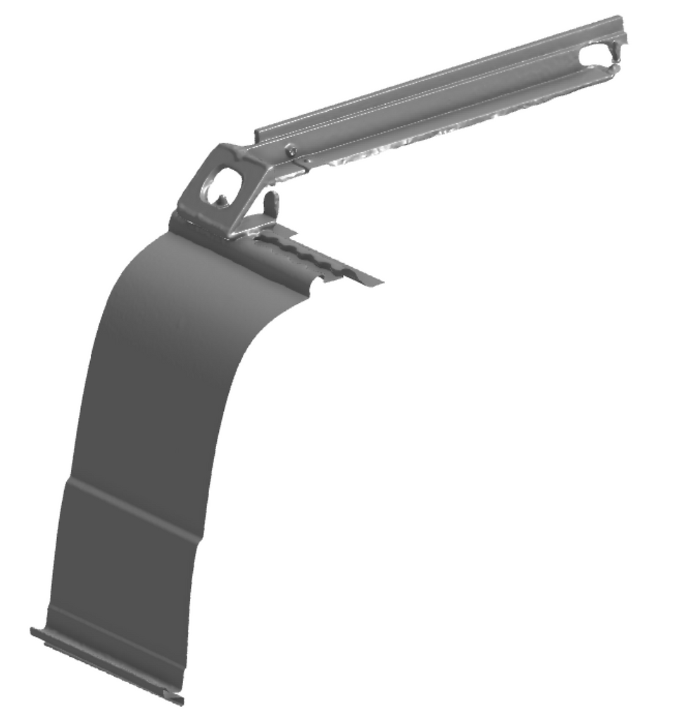
The 3D scan data was imported into OnShape, aligned using sketches and planes, and then started modeling the bracket over the scan, using the scan data as reference.

The gap at the bottom of the bracket between the bracket and the body panel is for an L track which will be glued to the side of the van, and the bracket will attach to the L track.
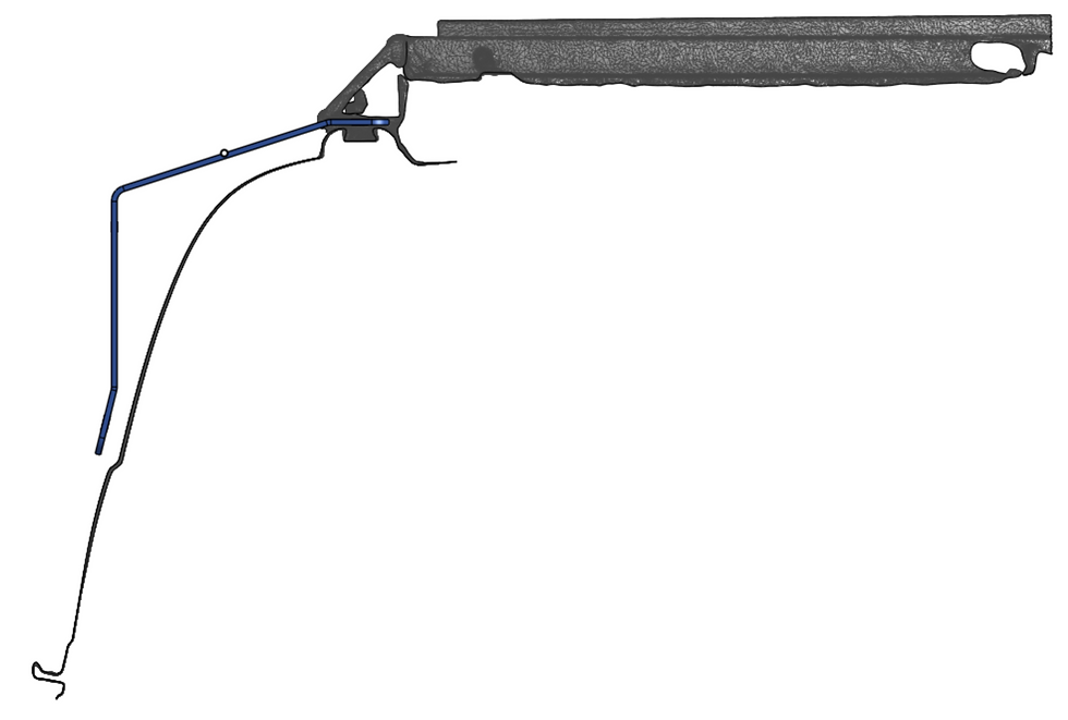
Here it's shown with the lower L track.

Here it's shown with the stock Fiamma bracket (light blue/green) which is normally used for vertical walls.

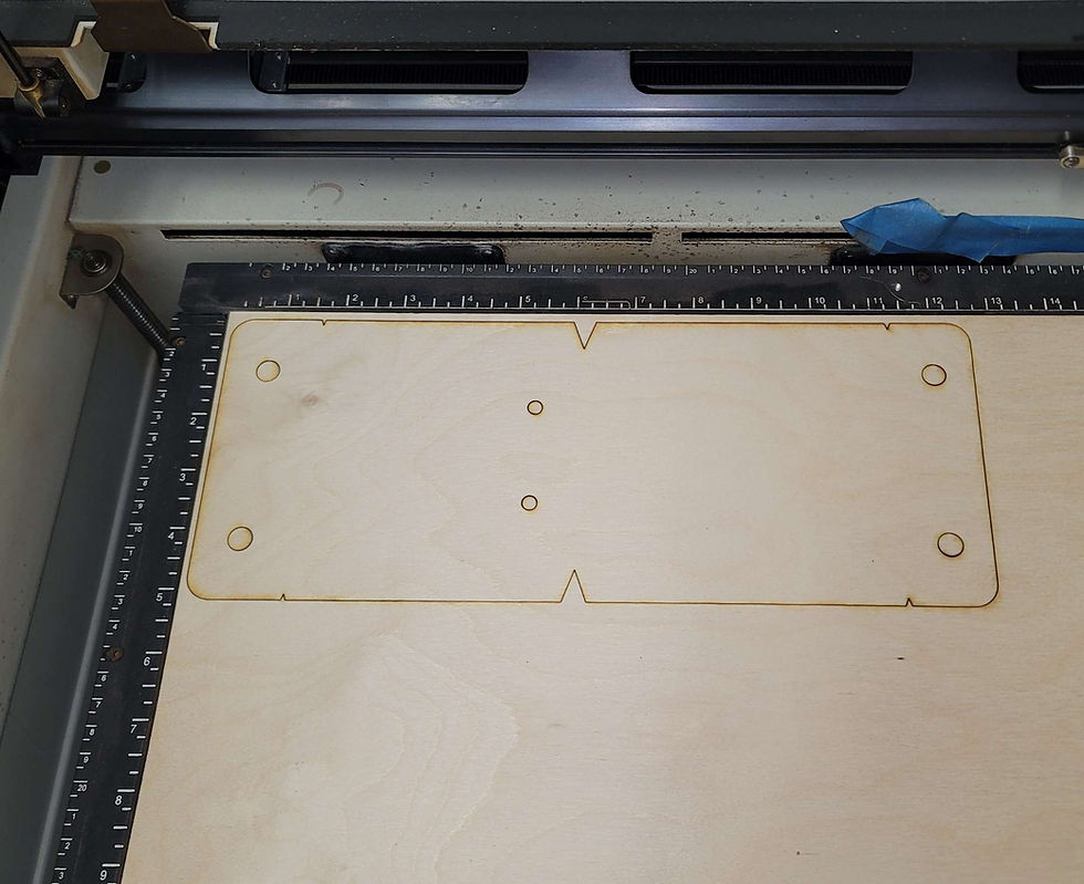
I laser cut the flat template. The v notches in the edges will make it easy to mark the bend line locations.
Laser cut a profile template to align the bends while bending it. The outline or the profile can be used as a bending guide.


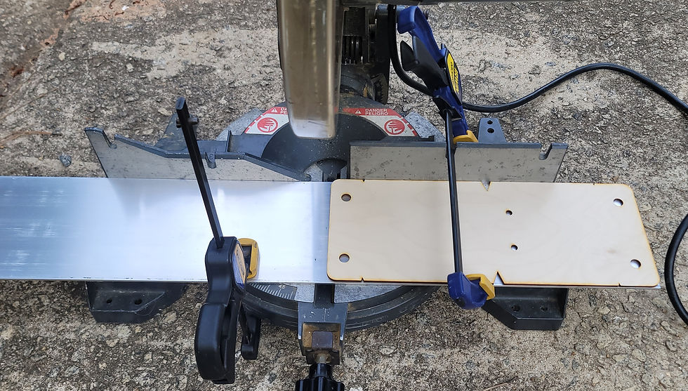
Using a miter saw to cut the aluminum. Go slow and it makes a clean cut. Using the template to set the length. Use clamps to hold the material in place.
After the cut has been made.

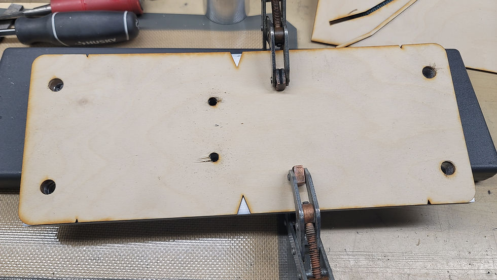
Three flat plates cut, now it's time to drill the holes. The laser cut wood template will be used to mark the hole locations.

Clamping all the parts together to drill the holes using the template.
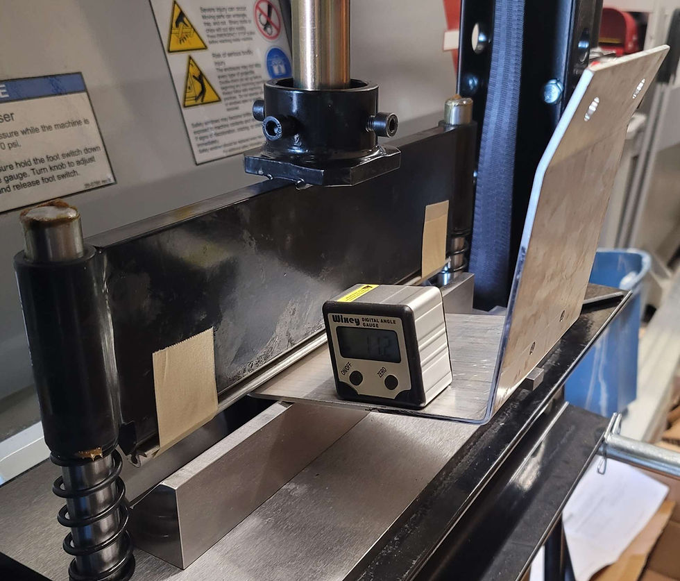
Bending the aluminum using the press brake. This is 6061, so had to heat the aluminum up with a torch at the bend line before bending. I read to draw the bend line with a sharpie, then heat until the sharpie line turns brown and disappears. Seemed to work well.
Added a larger radius piece to the sharp edge on the press brake blade. 6061 needs a large bend radius to prevent cracking.

Using the angle gauge is tricky. It need stop be bent a few degrees further because of rebound.
Using the laser cut template to check the bend angles.
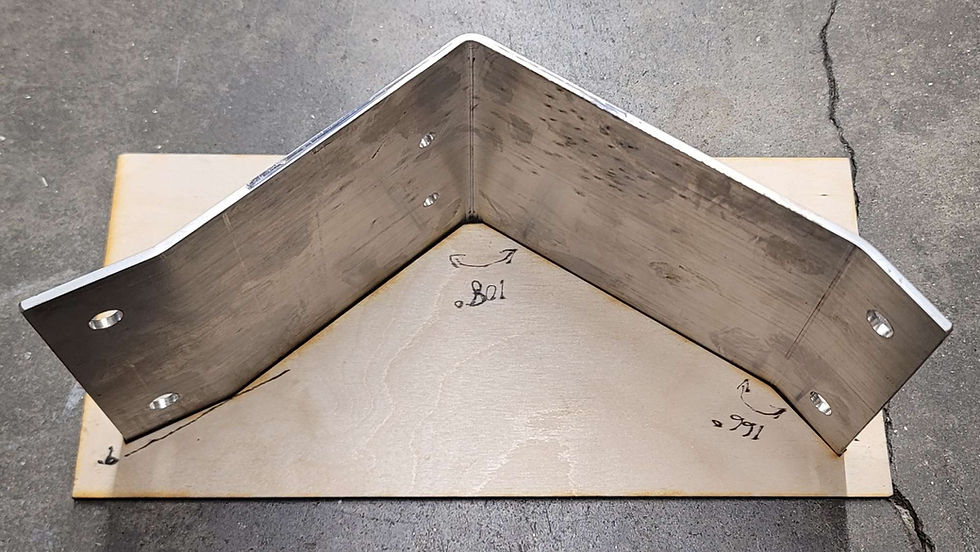
It fits straight through the template.

The inner cutout of the template also worked well to check the bends.


Comments